32+ electronic circuit block diagram
Here is available the huge collection of All Universal LCDLED TV Circuit Diagram Free Download. IoT pH Sensor Circuit Diagram.
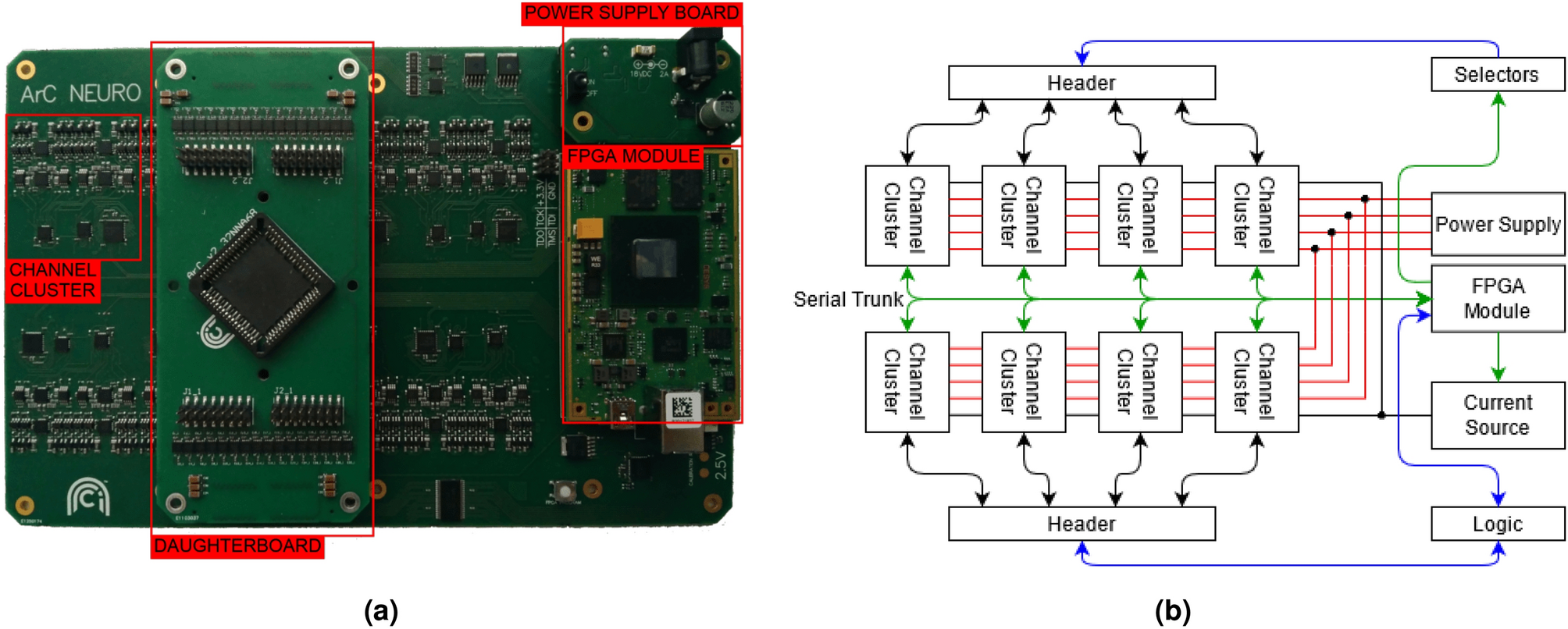
An Fpga Based System For Generalised Electron Devices Testing Scientific Reports
Two in One Door Bell.

. If you want to use an. Design and Development of Robot Arm System for Classification and Sorting Using Machine Vision The. Extend the built-in functionality with.
This can be made much. The project is intended to shut down the power supply when it is overloaded. We love to share all types of Electronics.
Usual circuit breaker like MCB is based on thermal. It is generally used while designing new systems or modifying the existing ones. A battery and resistor symbol is commonly shown in beginner electronics.
A Block diagram is defined as a major flowchart used in the engineering sector. The electronic circuit diagram of UM3561 IC as the simple circuit project is as given in the figure as electronics mini projects with circuit diagram. Download scientific diagram Electronic circuits block diagram from publication.
Electronic Circuit Breaker Project Working. Create diagrams visually by placing components with your cursor. All TV Circuit Diagrams are available free.
On the top left side you can see a regulated 5v power supply which is used to supply 5 volts to the ESP32 Module. A block diagram is a type of electrical drawing that represents the principle components of a complex system in the form of blocks interconnected by lines that represent their relation. An integrated circuit also referred to as an IC a chip or a microchip is a set of electronic circuits on one small plate chip of semiconductor material normally silicon.
A free user-friendly program for making electronic circuit diagrams. When the switch S1 or. The Electronic Block Diagrams solution for ConceptDraw DIAGRAM includes a set of diagrams samples and a large number of specialized electronic and electrical symbols of electronic.
The Electronics Circuits are composed of individual electronic components such as resistors transistors capacitors inductors and diodes. Schematic diagrams are the primary way that electronic and electric circuits are explained.

100w Transistor Power Amplifier Schematic Learn How To Build It Bright Hub Engineering

Fpv Wire Diagram Quadcopter Build Diy Drone Drones Concept
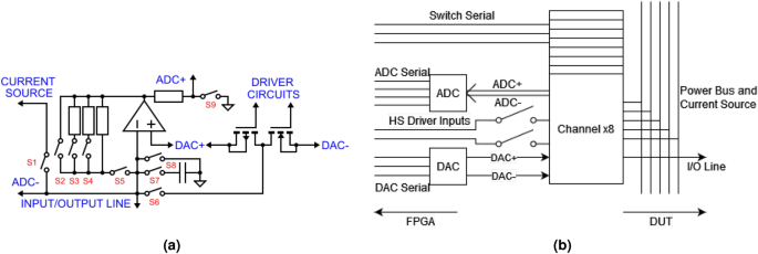
An Fpga Based System For Generalised Electron Devices Testing Scientific Reports
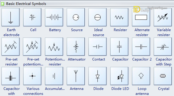
Basic Electrical Symbols Daily Engineering
Hitachi Zx135us 5a Hydraulic Excavator Electrical Hydraulic Circuit Diagram By Heydownloads Issuu

A Backlit Wall Switch Flip Flop Led Driver Circuit General Electronics Arduino Forum
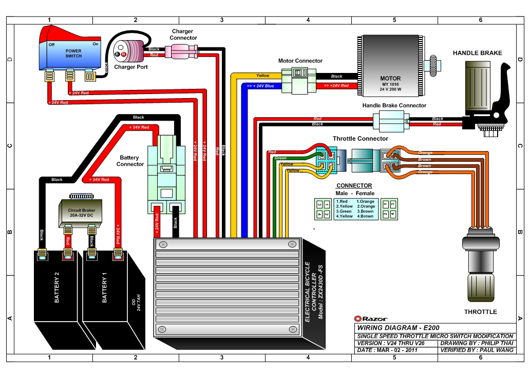
Razor Manuals

Hitachi Zh 210 A 210lc A Hybrid Excavator Electrical Hydraulic Circuit Diagram By Heydownloads Issuu

Hitachi Zh 210 6 210lc 6 Hybrid Excavator Electrical Hydraulic Circuit Diagram By Heydownloads Issuu
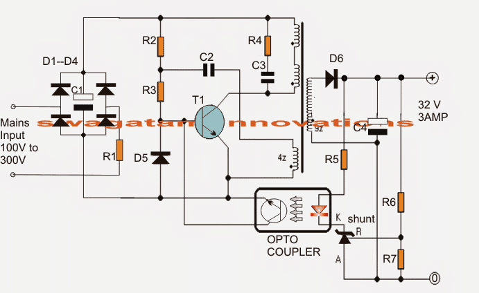
32v 3 Amp Led Driver Smps Circuit Homemade Circuit Projects
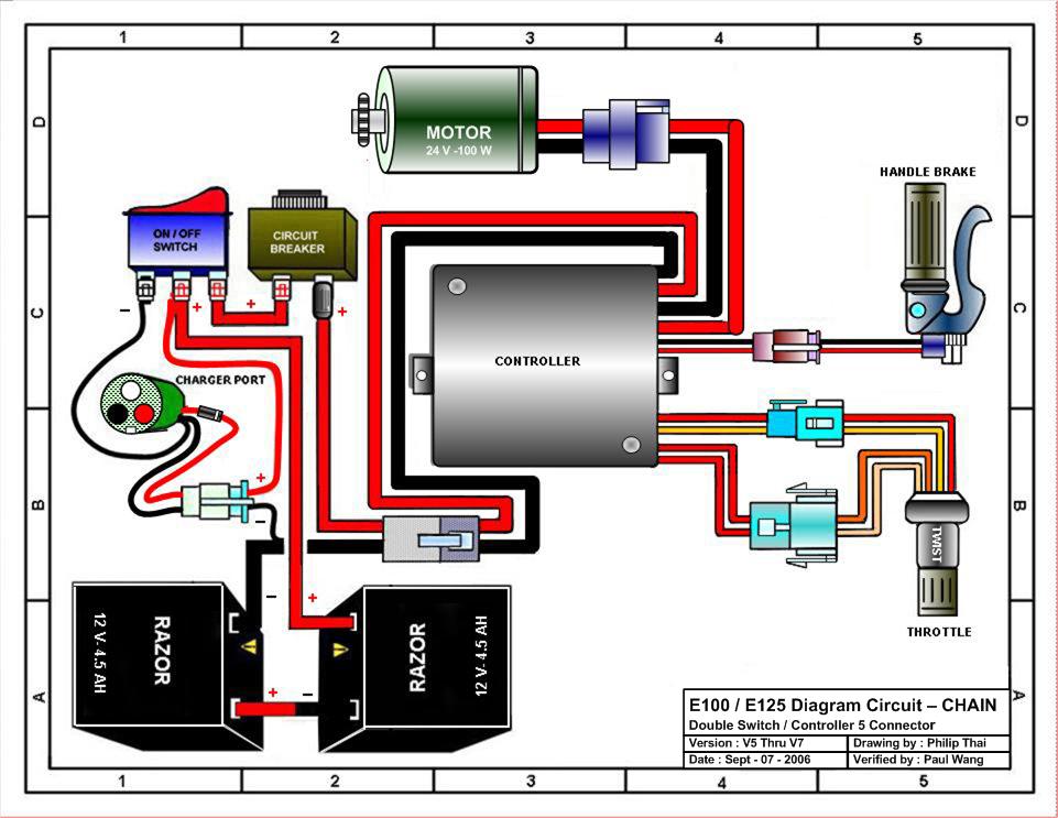
Razor Manuals

The Flip32 Is One Of The Better Quadcopter Controller Boards As It Uses A 32bit Controller With Some Great Software And Quadcopter Build Diy Drone Quadcopter

This Is A Short Guide Of The Skyline 32 Flight Controller For People Who Are New To The Board The Skyline 32 Flight Controll Drone Drones Concept Drone Design

Hitachi Zx210 6 210lc 6 210lcn 6 240n 6 Hydraulic Excavator Electrical Hydraulic Circuit Diagram By Heydownloads Issuu
A Survey And Comparative Analysis Of Multiply Accumulate Mac Block For Digital Signal Processing Application On Asic And Fpga Scialert Responsive Version

Hitachi Zh 210 A 210lc A Hybrid Excavator Electrical Hydraulic Circuit Diagram By Heydownloads Issuu

A Backlit Wall Switch Flip Flop Led Driver Circuit General Electronics Arduino Forum